CROMAFLOW WASTEWATER SYSTEMS
CromaFlow Secondary Treatment Equipment utilizes the Sequential Batching Reactor (SBR), process within 10 standard modular fiberglass vessels. With over 10,000 installations worldwide, CromaFlow treatment systems have consistently surpassed US EPA standards for secondary wastewater treatment of below 30 mg/l for both TSS and BOD5. From single family homes to small communities, CromaFlow offers 10 treatment processes from 500gpd to 15,000gpd. These modular units can be combined to treat wastewater flows of up to 200,000gpd. To assist in the treatment process CromaFlow also offers pre-treatment equipment, sludge thickening equipment, chlorine contact equipment and post equalization equipment.
Commercial Needs
The CromaFlow commercial wastewater treatment system is manufactured with corrosion proof materials and heavy duty PVC piping, incorporating SBR (Sequential Batch Reactor) technology to remove pollutants from applications such as hotels, industries, marinas, cruise terminals, power plants, and airports. Meeting the most demanding regulations, the CromaFlow wastewater treatment system utilizes proven SBR technology to efficiently remove pollutants found in effluents. CromaFlow also provides start up, servicing and spare parts to ensure years of efficient operation.
Residential Needs
The CromaFlow residential wastewater treatment system is manufactured with corrosion proof materials incorporating SBR (Sequential Batch Reactor) technology to remove pollutants from single homes, office buildings, developments and similar applications. The CromaFlow wastewater treatment system is easily installed underground. The systems are designed to operate to meet local environmental regulations with efficient waste treatment that does not produce offensive noise or odors.
SEWERAGE TREATMENT MODULES
"SBR" SECONDARY TREATMENT SYSTEMS
AERATED PRE-EQUALIZATION SYSTEMS
HOW IT WORKS!
The tank is divided into two (2) main sections. The first section is the solids retention section, which is separated from the remaining section of the tank by a stainless steel mesh screen. The second section of the tank has the aeration pumps and the dual (redundant) discharge pumps. The pumps are ontrolled by a time clock or PLC which alternates power to the aeration pumps every two hours. The timer or PLC is adjustable for the amount of programmed ON and OFF time for pump operation. Hand-Off-Auto switches are provided for confirming the proper mechanical operation of the motors or for manually overriding the control circuit.
SLUDGE PROCESSING SYSTEMS
HOW IT WORKS!
Provided as an ancillary process primarily for sludge management, the CromaFlow Aerated Sludge Processing Systems greatly reduce Bio solids produced. This translates to annual savings and allows for a more efficient operating Wastewater Treatment System.
The Sludge Processing Tank (SPT) receives excess sludge produced from each treatment Module via manual ball valve located in-line with the return activated sludge pipe. The operator, at his discretion, will manipulate the valves to direct the excess sludge to the SPT during routine site visits.
When the sludge tank is full, sludge thickening is accomplished by manually turning off the aeration pump(s) allowing the tank to settle, and manually pumping the supernatant. After the tank has settled, a decant pump is provided to send the clear supernatant back to the head of the treatment works. The decant pump is located at the back of manway number two and manually controlled by a separate breaker as noted on the control panel enclosure door. The decant pump is suspended from an adjustable chain and should be set by the operator to a height slightly above the sludge/supernatant interface. A float switch mounted directly to the pump will disengage the decant pump as the water level drops.
CHLORINE CONTACT SYSTEMS
CromaFlow Wastewater Treatment Systems applications may include the necessity for disinfection of treated effluent by means of chlorination. Non-corrosive fiberglass tanks are available to suit most volumes up through 75,000 GPD. Capacities of the chlorine contact tanks have been equated to treatment and discharge volume of the appropriate batch units with consideration for a minimum thirty (30) minute detention time in the chlorine contact tanks.
STORAGE & GENERAL PURPOSE TANKS
Non-corrosive fiberglass tanks are available for storage of effluent for the purpose of reuse or recycle.
TYPICAL CYCLE

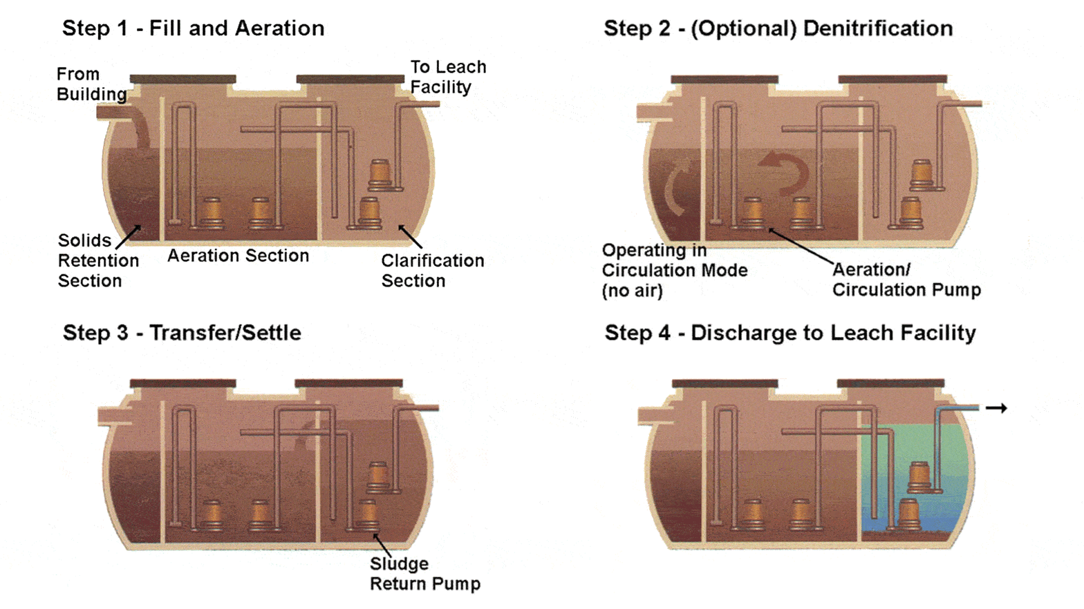
FILL; AERATION
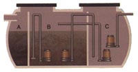
Flow enters the Solids Retention Section (A) that is separated by non-corrosive screen. Inorganic solids are retained behind the screen. Organic solids are broken by turbulence created with mixed liquor being forced through screen by submersible aeration pumps. This eliminates the need for mechanical comminution.
AERATION
Liquid and small organic solids pass through the screen into the continuing Aeration Section (B). Air and mixing are provided by submersible pumps with venture aspirators that receive air through pipe intake from the atmosphere.

DENITRIFICATION (OPTIONAL)
Provided by an anoxic period during the regular treatment cycle. CromaFlow units create anoxic conditions by closing the air intakes of the aeration pumps with electric valves. This stops aeration, but the system continues mixing.
TRANSFER/SETTLE
Treated mixed liquor is transferred by pumping to the Clarification Section (C). The transfer period overfills the Clarifier with the excess spilling through over-flow weirs back into the main Aeration Section. Transfer ceases and Clarifier ( C ) is isolated – solids separation occurs under quiescent conditions.

DISCHARGE
After settling, effluent is pumped out of the Clarifier ( C ) for discharge. Return sludge is pumped from the bottom of the Clarifier ( C ) back into the main Aeration Section (B) using a submersible pump or sludge can be wasted to a Sludge Processing Tank.

